

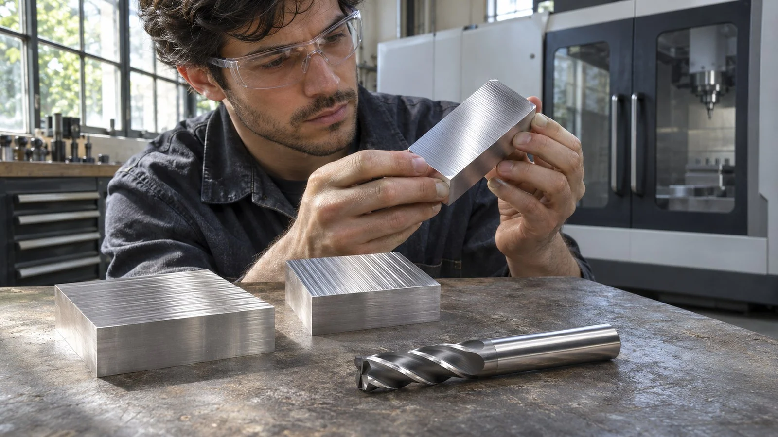
Climb milling generally suits a rigid setup that can control the cutter’s pull along the feed. Conventional milling better suits a leadscrew-and-nut arrangement where opposing cutting force maintains contact between the screw and nut. The defining difference in climb milling vs conventional milling is the cutting edge’s motion relative to workpiece feed at contact.
Climb Milling vs Conventional Milling: Key Differences
In the peripheral engagement considered here, climb milling moves the cutting edge with workpiece feed at contact, and chip thickness decreases through the cut. Conventional milling moves the edge against workpiece feed, and chip thickness increases. Identify the direction at the engaged cutting edge rather than from spindle rotation alone.
| Comparison | Climb Milling | Conventional Milling |
|---|---|---|
| Other name | Down milling | Up milling |
| Cutting-edge motion at contact | Same general direction as workpiece feed | Opposite to workpiece feed |
| Chip progression | Relatively thick at entry, becoming thinner | Near zero at entry, becoming thicker |
| Feed-force behavior | Can pull the workpiece along the feed | Can keep the nut loaded against the screw in the described leadscrew arrangement |
Read the Cut at the Contact Point
Climb Milling
Same Direction at Contact
- Top Arrow
- Workpiece Feed
- Lower Arrow
- Cutting Edge at Contact
- Chip Progression
- Thick to Thin
Conventional Milling
Opposite Direction at Contact
- Top Arrow
- Workpiece Feed
- Lower Arrow
- Cutting Edge at Contact
- Chip Progression
- Thin to Thick
Diagram Scope: Local cutting-edge motion at the contact point only; not a full toolpath or force diagram.
These relationships describe the local cutting engagement. They don’t establish a universal force direction for every toolpath or workholding arrangement.
Climb Milling: Strengths, Drawbacks, and Uses
Engagement. In climb milling, the tooth enters with a relatively substantial chip and removes progressively less material as it passes through the engagement. An end mill cutting a pocket wall is a peripheral machining application where you can assess this relationship at the tool’s outside cutting edges. This is the relevant application when considering the side-cutting action of a flat end mill.
Strengths and drawbacks. The tooth begins cutting without the near-zero chip entry associated with conventional milling. The important tradeoff is the tendency to pull the workpiece along the feed. If that force takes up uncontrolled backlash, the table can advance unexpectedly into the cutter and disrupt the cut. A force component toward a supporting surface may also occur in the described engagement, but that doesn’t replace secure workholding.
Best uses. Climb milling is a suitable choice when machine control, fixture rigidity, and workpiece rigidity allow the engagement. For an end mill machining a wall, evaluate the cutting side and the machine’s ability to resist unwanted movement. Material and feature geometry remain part of that decision; selecting climb milling alone doesn’t establish suitable cutting parameters.
Conventional Milling: Strengths, Drawbacks, and Uses
Engagement. In conventional milling, cutting-edge motion opposes workpiece feed at contact. Chip thickness begins close to zero and grows as the tooth advances through the cut. That thin entry can involve rubbing before the edge develops a chip.
Strengths and drawbacks. In the leadscrew-and-nut arrangement described here, conventional milling’s opposing force keeps the nut pressed against the screw. That explains its usefulness where climb cutting could pull the table across screw clearance. Its entry behavior is the tradeoff: the edge starts at very low chip thickness. Conventional milling doesn’t remove backlash or make a worn machine safe to operate.
Best uses. Conventional milling suits an operation where the machine’s guidance and actual drive condition favor keeping the screw and nut loaded in this way. Treat that as a condition of the particular setup. Neither a manual-machine label nor a CNC label establishes the condition of the axis drive, and CNC control alone doesn’t establish that backlash is absent.
Milling Direction: Which Should You Choose?
Choose Climb Milling If
- The machine can control the pull generated along the feed.
- The machine, fixture, and workpiece provide adequate rigidity for the operation.
- The machine and tooling guidance permit climb cutting for the intended engagement.
Choose Conventional Milling If
- The leadscrew arrangement benefits from opposing cutting force maintaining screw-and-nut contact.
- The machine’s instructions favor conventional cutting for its drive condition and the planned operation.
When selecting tooling for climb milling vs conventional milling, we recommend checking the individual cutter’s intended application alongside the machine requirements. A milling-direction choice doesn’t establish an end mill’s geometry, material compatibility, or permitted cutting conditions.
Before programming the pass, mark the engaged side of the cutter, the local cutting-edge motion, and the workpiece-feed direction on a sketch. Then check the planned material engagement and cutting parameters against the machine and tool guidance. This connects the direction label to the actual wall you intend to machine.
FAQ
Is Climb Milling Also Called Down Milling?
Yes. Climb milling and down milling describe the engagement in which cutting-edge motion follows workpiece feed at contact.
Does Spindle Rotation Alone Identify Milling Direction?
No. Compare the cutting edge’s local motion with workpiece feed at the contact point: matching directions indicate climb milling, while opposing directions indicate conventional milling.
Is a Full-Width Slot Entirely Climb Milling?
Don’t assign the same milling direction to both walls from a toolpath label alone. Assess the cutter’s local engagement at each wall.