

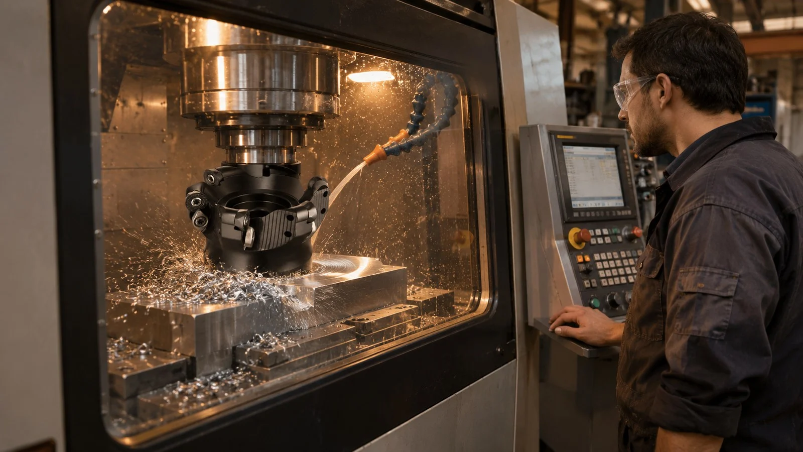
Chip thinning in milling occurs when a narrow radial cut produces a chip thinner than the programmed feed per tooth. For a 90-degree cutter engaged at less than half its diameter, you can increase feed per tooth to maintain a chosen maximum chip thickness; at half diameter, this particular radial correction is 1.
How Radial Chip Thinning Changes Feed
Radial chip thinning is the reduction in maximum chip thickness that occurs when a 90-degree milling cutter engages less than half its diameter. As the cut becomes narrower, the programmed feed per tooth must increase to maintain the same maximum chip thickness. The adjustment depends on the cutter diameter and radial width of cut.
The chip changes thickness as the cutting edge moves through the workpiece. At a lighter radial engagement, the edge leaves the cut before reaching the thickness it would produce at half-diameter engagement. Feed per tooth and maximum chip thickness therefore aren’t interchangeable at every width of cut.
Chip Thinning Formula for 90-Degree Milling
For a cutter with 90-degree geometry and a radial width of cut no greater than half the cutter diameter, calculate the required feed per tooth as:
fz = hmax ÷ [2 × √((ae ÷ D) × (1 − ae ÷ D))]
Where:
- fz = feed per tooth, in mm/tooth
- hmax = target maximum chip thickness, in mm
- ae = radial width of cut, in mm
- D = cutter diameter, in mm
Use the same length units for ae and D. The expression inside the brackets is the portion of feed per tooth that becomes maximum chip thickness at that engagement.
The relation follows from the cutter geometry in ISCAR’s milling applications guide: hmax = fz × sin(AE), where AE = arccos((r − ae) ÷ r) and r = D ÷ 2. Substituting the diameter and simplifying gives the square-root expression above.
At 50% radial engagement, the bracketed factor is 1, so fz = hmax. Below 50%, the factor is smaller than 1, so the feed per tooth needed for the same maximum chip thickness is higher.
Feed Adjustment Example
ISCAR gives an example using a 32 mm end mill cutting an 8 mm shoulder. The radial engagement is therefore 25% of the cutter diameter. Its target average chip thickness is 0.08 mm; the example assumes that average thickness is half the maximum, giving a target hmax of 0.16 mm.
| Step | Calculation | Result |
|---|---|---|
| Radial engagement | 8 ÷ 32 | 0.25 |
| Chip-thickness factor | 2 × √(0.25 × 0.75) | Approximately 0.866 |
| Feed per tooth | 0.16 ÷ 0.866 | Approximately 0.185 mm/tooth |
The unrounded result is approximately 0.18475 mm/tooth. ISCAR rounds it to 0.185 mm/tooth. The conversion from average to maximum chip thickness is an assumption in that example, so don’t substitute a target average thickness directly for hmax in the formula.
Once you have a suitable feed per tooth, calculate the programmed table feed using spindle speed and the number of cutting teeth:
Table feed (mm/min) = fz (mm/tooth) × cutting teeth × spindle speed (rev/min)
When to Use the Correction
Check the cutter geometry and actual radial width of cut before applying the formula. It covers the stated 90-degree geometry at ae ≤ 0.5D; cutters with other geometries need an applicable calculation for their cutting edge and engagement.
The correction maintains a selected maximum chip thickness as radial engagement changes. It doesn’t choose that target for you. Use the cutter’s applicable recommendations when selecting the target and checking the resulting feed.
If you’re comparing cutters for a machining operation, confirm the geometry and cutting conditions before transferring a feed calculation from one tool to another. For chip thinning milling, record the cutter diameter, planned width of cut, target maximum chip thickness, tooth count and spindle speed alongside the programmed feed.
FAQ
When Does Radial Chip Thinning Occur?
For the 90-degree geometry described here, radial chip thinning occurs when the width of cut is less than 50% of the cutter diameter.
Does Chip Thinning Change Spindle Speed?
The radial correction calculates feed per tooth from the target maximum chip thickness and engagement. Spindle speed is a separate input used with feed per tooth and tooth count to calculate table feed.
Can I Use Average Chip Thickness?
You can use it only after converting it to the maximum chip thickness required by the formula. In the ISCAR example, average thickness is assumed to be half the maximum; that assumption belongs to the example’s calculation.