

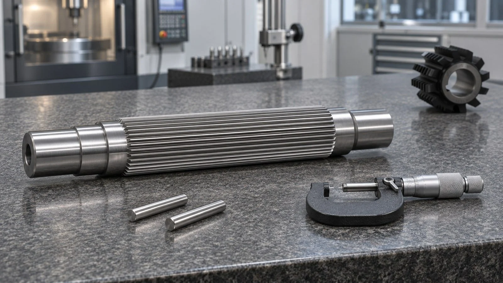
Spline measurement over pins gives an inspector a dimensional check of a straight external involute spline by placing pins in tooth spaces and measuring across them. Use the pin diameter and measurement conditions specified for the part; the result is meaningful only when interpreted against the drawing’s limits and notes.
Spline Measurement Over Pins: What It Measures
For a straight external involute spline, measurement over pins is the distance across two pins placed in opposite tooth spaces. The measured value depends on the pin diameter, so record which pins were used. The dimension can help check actual tooth thickness. It does not, by itself, establish fit or replace other acceptance checks.
The drawing may label the dimension “over pins,” “over balls,” or with an abbreviation such as MOP or MOW. Read the callout and its notes together: a listed value may be for reference, while acceptance can depend on separate checks for actual and effective tooth size. The SplineGen drawing guide explains how to distinguish these callouts and checks.
Read the Drawing Before Measuring
Find the spline definition, the over-pins dimension, its tolerance or limits, and any reference note. Confirm the specified pin diameter and units. If the drawing doesn’t identify the pin size or explain how the dimension is used, don’t substitute a convenient pin and treat the result as an acceptance value; resolve the requirement through the applicable drawing or inspection instructions.
Actual and effective tooth size describe different checks. Pins can be used to assess actual tooth thickness, while a composite GO gage checks effective tooth thickness. Neither result should be assumed to prove the other characteristic or overall fit. Apply the acceptance criteria stated for the part and use each required check for its stated purpose.
Set Up Pins and Measuring Equipment
Before measuring, check that the part, pins, and contact surfaces are clean and free of debris that could affect contact. Use pins of the specified diameter and a measuring instrument with current calibration. For a diametral measurement over pins or balls, opposed measuring inserts are one equipment example; a master can set the nominal size.
- Confirm the drawing callout, units, specified pin diameter, and acceptance limits.
- Clean the part, pins, and measuring contact surfaces.
- Use the specified pins and a currently calibrated instrument.
- Follow the drawing and gauge instructions for seating, alignment, measuring force, and recording the result.
These are setup checks, not a substitute measuring procedure. Exact pin seating and instrument use depend on the applicable drawing and gauge instructions. A shaft shown with loose pins may illustrate the parts involved, but it does not establish how to position or measure them.
Odd Tooth Counts and Opposed Spaces
The two-pin arrangement relies on spaces directly opposite one another. An odd tooth count has no diametrically opposite spaces, so don’t assume that the same placement or an informal correction applies. Use the drawing and inspection instructions for the specified measurement method and acceptance decision.
Keep Tooling Separate From Inspection
A spline hob is manufacturing tooling. Wencerl’s Involute Spline Hob m1 a30° M42 AA (2) is an example of spline manufacturing tooling.
After measuring, record the pin diameter, reading, and drawing revision together on the inspection sheet.
FAQ
What Does Measurement Over Pins Show?
It records the distance across pins in opposite spaces on an external spline. The value depends on the specified pin diameter and must be interpreted with the drawing’s notes and acceptance criteria.
Can Over-Pins Measurement Confirm Fit?
No single over-pins result establishes fit. It can check actual tooth thickness, while effective tooth thickness may require a separate composite gage check.
What If the Drawing Marks It Reference?
Treat a reference dimension as informational, not as an acceptance limit. Follow the drawing’s separate controlling limits and required inspection checks.