

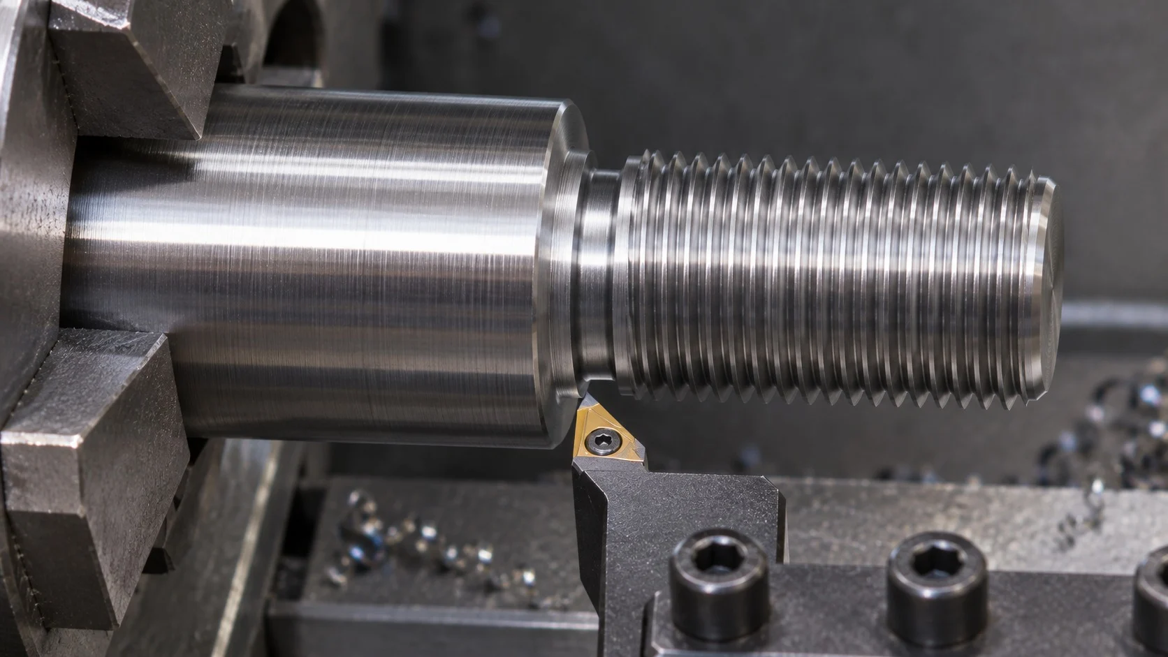
A thread relief groove provides space at the end of a thread for tool runout or mating-part clearance. Near a shoulder or inside a blind bore, plan the relief, usable thread length, and tool exit together. The drawing and applicable specification should define the finished geometry, while the process plan establishes how to machine and inspect it.
Confirm the Purpose and Drawing Requirements
Start with the thread callout, required usable thread length, shoulder location, and bore geometry. Establish whether the relief provides tool clearance, mating-part clearance, or both.
For the groove, identify the specified diameter, width, and axial position relative to the drawing datum. Include any specified corner radius and associated tolerances. Review these requirements alongside the material and mating-part geometry so the relief and functional thread are treated as connected features.
Resolve missing or conflicting requirements with the design authority before finalizing the program. A familiar groove size does not establish what this particular part requires.
Choose a Machining Method That Fits the Part
For a turned feature, check tool access before choosing the operation sequence. Near an external shoulder, review holder clearance, adjacent faces, and workpiece support. Inside a blind bore, check bar reach, bore clearance, chip evacuation, and the space needed for withdrawal.
Review insert and holder geometry together. Our grooving insert catalog on the Wencerl website provides available insert options. Verify the selected combination’s width, corner geometry, reach, and clearances against the drawing and setup.
Programmed pull-out also needs attention. The Haas threading-cycle manual illustrates shoulder threading with an optional exit chamfer and a case with a relief. Check the actual control manual to establish how the selected cycle ends the cutting pass and withdraws the tool. Confirm that its exit motion fits the available clearance and preserves the specified thread end condition.
Plan the Thread-To-Groove Transition
The transition must accommodate the planned tool exit while retaining the required usable thread. Review the groove tool’s width and corner radius alongside the threading tool’s path, holder clearance, and approach and retract motions.
Consider an external thread ending beside a shoulder where the drawing already specifies a relief. Use that defined groove as the basis for planning the grooving and threading operations. Check that the programmed exit fits within the available space and that the required usable thread length remains intact.
Now consider a blind-bore drawing that requires usable thread close to the bore end but provides no room for the planned runout. Bring the thread-length requirement, bore geometry, and proposed exit motion to the design authority. Resolve the conflict through an approved thread-end condition or design revision before cutting.
In both cases, establish how the groove and thread end will be measured before releasing the setup.
Set Up, Cut, and Inspect in a Controlled Sequence
Inspect the cutting edge and holder, clean seating surfaces, and secure the workpiece. Verify offsets and review the complete approach, cutting, and withdrawal paths. Simulate or safely prove the motion around the shoulder, bore end, chuck, and fixtures. Use cutting data appropriate to the selected tool, material, and operation.
After machining, inspect groove diameter and width, axial position relative to the drawing datum, and any specified corner radius. Separately verify the required usable thread length and inspect the thread with the specified gauge or measurement method. Check the transition for incomplete or damaged thread and for burrs that could interfere with assembly. Deburr within the drawing’s permitted limits.
Record the setup and inspection results for repeat production. Keep guards in place and follow the machine builder’s safety procedures. Stop the machine before clearing chips or investigating unusual vibration, noise, or tool damage.
FAQ
Does Every Threaded Shoulder Need a Relief Groove?
No. The requirement depends on the drawing, mating geometry, tooling, and specified thread end condition. Confirm these together during process planning.
Can I Use the Groove to Shorten the Required Thread Length?
A relief does not authorize a change to usable thread length. Any change to that requirement needs design approval.
Should the Groove Be Machined Before or After Threading?
Choose the sequence around tool access, the thread-to-groove transition, and inspection requirements. Verify that the completed groove and thread both meet the drawing.