

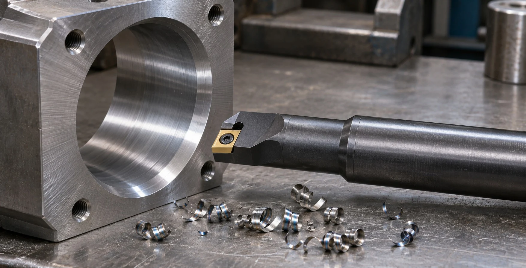
Poor chip evacuation in boring often appears as chip packing, surface damage, unstable cutting or repeated tool stoppages. In a restricted bore, chips have limited room to leave the cutting zone, so diagnosis should consider the full setup: bore depth and diameter, bar reach, insert geometry, cutting conditions and coolant delivery. Changing parameters without identifying the obstruction can make the process less stable.
Map the Space Around the Cutting Zone
Start with the part drawing and setup. Record bore diameter, depth, entry conditions, shoulder locations, interruptions and whether the hole is through or blind. Compare these dimensions with the boring bar, head, insert and holder envelope. Check the clearance available for chips to move past the tool and out of the bore.
A long reach or small bore can restrict both chip flow and tool stiffness. Confirm that the selected bar and insert are intended for the required diameter and depth. Verify the tool’s orientation, overhang and clearance against the manufacturer’s guidance. Do not assume that a tool that fits the opening has adequate chip space or a suitable reach for stable machining.
Read the Chips and Surface Evidence
Observe chip shape, color and consistency under the shop’s safe inspection procedure. Long chips may wrap around the tool or workpiece; compacted chips may remain in a blind bore; and broken or recutting chips can mark the surface. These are clues, not definitive diagnoses. Also inspect for chatter, built-up material, edge damage and changes in bore finish or size.
Stop the machine before clearing chips, and follow site procedures for handling sharp or hot material. Never pull chips from a rotating tool or reach into an unguarded cutting zone. If chips are packing, identify where they accumulate and whether the tool’s flute or coolant path is obstructed before restarting.
Check Tool Geometry and Coolant Delivery
Review the insert geometry, chipbreaker and cutting edge against the workpiece material and operation. The chip control feature must suit the material and cutting conditions; a geometry chosen for a different application may produce chips that are difficult to manage in a confined bore. Check insert installation, edge condition and the boring tool’s recommended operating range.
Assess coolant or lubrication delivery at the cutting zone. Confirm that the selected arrangement reaches the edge and that passages are open, where applicable. The correct pressure, flow and fluid choice depend on the tool, machine, material and operation. Follow manufacturer instructions rather than applying a generic coolant setting.
Adjust the Process Methodically
Use tool-specific cutting data as the starting point. If a chip-control adjustment is needed, change one approved variable at a time and inspect the resulting chip form and bore quality. Feed, speed and depth of cut affect chip formation, but permissible changes depend on the insert, bar, material and machine. Consult the toolmaker when the recommended range does not produce manageable chips.
For a deep or blind bore, evaluate whether the operation sequence or tool arrangement can provide better chip access. Any change to pecking, retract motion, coolant strategy or tool path must be checked against the machine and tool instructions and validated for the part. Maintain guarding, secure workholding and use the machine’s approved chip-clearing procedure.
Record the bore condition, tool setup, material, parameters and observed chip behavior. This makes it easier to distinguish a recurring geometry constraint from tool wear or a process change. Wencerl’s metal cutting tool range can support a discussion about boring tools and chip control when supplied with the bore drawing, material, machine and current symptoms.
FAQ
Why do chips jam in a boring operation?
Common contributors include limited bore clearance, long chips, deep or blind geometry, unsuitable tool geometry, restricted coolant delivery or an unstable setup. Inspect the actual cutting zone to identify the cause.
Should I increase coolant pressure to clear chips?
Only if the tool and machine manufacturers approve the arrangement and operating conditions. Verify delivery and consult the supplier before changing pressure or flow.
Is a longer boring bar the solution for a deep bore?
Reach is only one factor. Check bar suitability, rigidity, insert geometry and chip clearance together, using manufacturer guidance for the specific setup.