

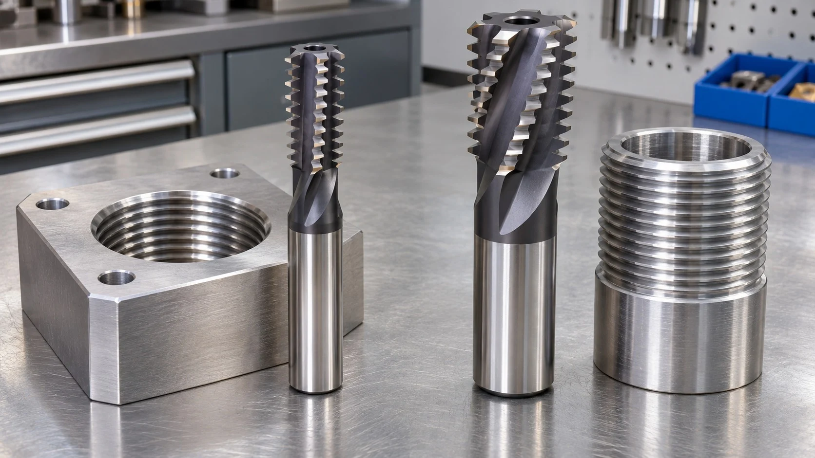
Internal thread milling cuts inside a prepared bore, while external thread milling cuts around a prepared outside diameter. Both use a rotating cutter following a helical path. The main setup differences involve cutter access, clearance, workholding and chip evacuation.
| Setup Factor | Internal Thread Milling | External Thread Milling |
|---|---|---|
| Blank Preparation | Prepare the bore to the required pre-thread dimensions | Prepare the outside diameter to the required pre-thread dimensions |
| Cutter Access | Allow entry into the bore and reach to the full thread length | Allow travel around the circumference and along the thread length |
| Clearance | Check bore walls, bottom clearance and the tool assembly | Check shoulders, adjacent features and fixtures |
| Chip Evacuation | Account for confined space, especially in blind holes | Check for obstructions around the exposed cutting area |
| Feed Geometry | Tool-center path is smaller than the thread-diameter path | Tool-center path is larger than the thread-diameter path |
How Internal Thread Milling Works
Prepare the bore to the drawing and toolmaker’s requirements. Confirm that its diameter and depth accommodate the specified thread, cutter entry and planned path. Check usable cutting length and reach separately from overall tool length.
Verify clearance for the cutter, shank, holder and spindle nose throughout entry, cutting and withdrawal. For blind holes, include bottom clearance and space for the approach and retract moves. Plan coolant delivery and chip evacuation around the available bore space, particularly where chips could collect below the cutter.
How External Thread Milling Works
Prepare the blank’s outside diameter to the specified pre-thread size and support the workpiece against cutting forces. The fixture must leave access around the circumference and over the required thread length.
Check the cutter and tool assembly against shoulders, adjacent features and clamps throughout the operation. Confirm that entry and exit moves fit within the available space at each thread end. External cuts generally offer more open chip space, but nearby features can obstruct discharge. Plan coolant delivery and chip removal around those constraints.
Program the Helical Path and Centerline Feed
Start with the drawing’s thread form, nominal diameter, tolerance class, handedness, number of starts and thread length. Lead is the axial travel per programmed orbit. Pitch equals lead on a single-start thread. Confirm the required lead, spindle direction and interpolation direction for the operation.
Centerline feed correction differs by location. For internal threading, the tool-center path is smaller than the cutting path at the thread diameter. For external threading, it is larger. Check how the recommended feed is defined and whether the CAM system or controller already accounts for this geometry. Apply the correction once to avoid double compensation.
Use the selected tool’s cutting data and verify smooth roll-in and roll-out moves within the available clearance. The feed and path relationships are illustrated in Sandvik Coromant’s technical guide.
Prove the Setup and Inspect the First Piece
Inspect the cutter and holder, clean contact surfaces, and verify tool length and runout using the established setup procedure. Simulate or prove the complete path, including compensation, approach and retract moves, before running a controlled first piece.
Use the drawing-specified gauge or measurement method and acceptance criteria. Confirm thread size and tolerance class, pitch or lead, handedness, full-form thread length, and any thread-end or runout requirements. Where GO/NO-GO gauging is specified, use the matching internal or external gauge and prescribed acceptance procedure. Investigate failed checks through tool selection, offsets, path geometry, workholding and wear before adjusting settings.
The drawing determines whether the thread is internal, in a bore, or external, on an outside diameter (OD). For an internal setup, confirm that the tool reaches the specified usable thread length with clearance throughout entry, the helical path and exit. For an external setup, confirm clearance around the circumference over that length, including at shoulders and clamps.
When reviewing our thread milling cutters at Wencerl, confirm that the selected tool’s documented ID/OD application, size range and reach match the drawing and setup.
FAQ
Is Internal Thread Milling Harder Than External Thread Milling?
Restricted access and chip evacuation can make internal setups more demanding, particularly in blind holes. Actual difficulty depends on geometry, tool reach, workholding and process planning.
Can the Same Thread Mill Cut Internal and External Threads?
Some tools support both applications. Confirm the selected tool’s documented geometry, thread form, diameter range and recommended path for each operation.
How Should a Milled Thread Be Inspected?
Follow the drawing’s gauge, measurement method and acceptance criteria. Check the required full-form length and thread-end conditions alongside functional fit. A visual check alone cannot confirm compliance.